
Why Is a Balancing Valve Important in HVAC Systems?
A balancing valve is a small component with a large influence on HVAC performance. It controls water flow through heating and cooling circuits, helping each terminal unit receive its designed share. Without proper balancing, one office may feel cold while another remains uncomfortably warm. Pumps may also work harder than necessary, increasing energy use and operating noise.
In real mechanical rooms, the problem can be surprisingly ordinary. A valve may be left near its factory setting, even after the system layout changes. A clogged strainer, incorrect pipe size, or inaccurate flow measurement can create similar symptoms. Technicians commonly check differential pressure, design flow, valve position, and temperature differences during commissioning. These details reveal whether the system is distributing water effectively. Small adjustments can change coil performance within minutes. Yet balancing is not a magic fix.
The importance of a balancing valve becomes clearer in variable-flow systems. It supports stable control, protects equipment performance, and improves comfort across different loads. Proper selection must match the pipe size, flow range, pressure conditions, and control strategy. Qualified HVAC professionals should verify settings with calibrated instruments and follow project specifications. Manufacturer data and recognized engineering guidance also matter. A careless adjustment can hide a deeper design or maintenance issue. That limitation deserves attention. Good balancing combines field experience, accurate measurements, and honest troubleshooting. When these elements work together, the HVAC system becomes quieter, more predictable, and easier to maintain.
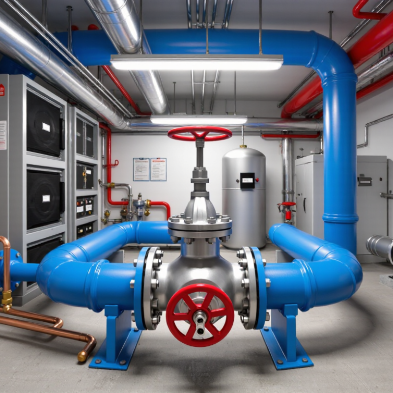
What Is a Balancing Valve? Regulating Design Flow, ΔP, and Coil Capacity
A balancing valve regulates water flow through an HVAC coil, helping the system deliver its design performance. The design flow rate is not a random setting. It matches the coil’s required heat transfer capacity. When flow is too low, the coil may not meet the room load. When flow is too high, pumps consume extra energy and control becomes unstable.
Differential pressure, or ΔP, is equally important. A valve needs enough pressure difference to control flow accurately, but excessive ΔP can create noise and unnecessary throttling. During commissioning, technicians measure flow and pressure near the coil. They compare readings with the design schedule, then adjust the valve carefully. I have seen systems appear balanced at one branch while another branch still lacked flow.
Coil capacity depends on water flow, entering water temperature, air conditions, and heat exchanger cleanliness. The valve cannot correct every problem. A dirty strainer, trapped air, or an incorrectly sized pump can produce misleading readings. This is where practical judgment matters. A calculation can be correct, yet the installation may not be. Rechecking the valve after control changes is worthwhile. Small adjustments often reveal larger system issues. Not every “balanced” system stays balanced.
Why Is a Balancing Valve Important in HVAC Systems? - What Is a Balancing Valve? Regulating Design Flow, ΔP, and Coil Capacity
| HVAC Parameter | Typical Design or Operating Range | How the Balancing Valve Affects It | Practical Verification Method | System Benefit |
|---|---|---|---|---|
| Design Water Flow | Calculated from the coil load and water temperature difference; commonly 0.05–0.30 L/s per terminal coil | Sets and limits the water flow through the branch or coil circuit | Measure flow with a calibrated balancing instrument or flow meter | Prevents over-flow in near branches and under-flow in remote branches |
| Differential Pressure (ΔP) | Often 10–50 kPa across a terminal circuit, depending on system design and valve selection | Introduces a controlled pressure loss to achieve the required flow | Measure pressure at the valve test points or across the circuit | Improves hydraulic stability and supports repeatable commissioning |
| Coil Heat Transfer Capacity | Heating or cooling output depends on water flow, entering-air condition, and water temperature | Maintains the water flow required for the coil to deliver its scheduled capacity | Compare measured flow and air or water temperatures with the design schedule | Reduces complaints caused by rooms being too warm or too cold |
| Valve Authority | A control-valve authority of approximately 0.3–0.5 is commonly targeted for stable modulation | Affects the pressure relationship between the control valve and the rest of the circuit | Calculate control-valve ΔP divided by total circuit ΔP at design flow | Helps prevent hunting, poor controllability, and excessive valve movement |
| Flow Measurement Accuracy | Depends on valve type, test instrument, installation conditions, and manufacturer calibration data | Provides a defined measurement point for commissioning and troubleshooting | Use the valve’s calibrated flow chart together with measured ΔP | Makes balancing results more consistent and traceable |
| System Energy Use | Pump energy rises as required flow and system pressure increase | Prevents unnecessary design-flow excess that can increase pump and fan-related operating costs | Review pump speed, differential pressure, and terminal flow after balancing | Supports lower pumping power while maintaining required terminal performance |
| Noise and Erosion Risk | Excessive velocity and high pressure drop can increase water noise and valve wear | Controls excessive flow and helps keep valve pressure loss within the design limit | Check measured velocity, ΔP, acoustic conditions, and valve sizing | Improves occupant comfort and component service life |
| Commissioning Status | Final readings should be compared with the approved design flow and pressure schedule | Allows the circuit to be adjusted, recorded, and locked or marked after testing | Record valve setting, measured flow, ΔP, temperatures, and date of test | Provides documented evidence that the hydronic system is balanced |
Note: Actual flow rates, differential pressures, valve settings, and temperature differences must be selected from the project design calculations, equipment schedules, pipe sizing, and applicable HVAC standards.
Related Posts
-

Understanding Pressure Valves and Their Impact on Industrial Safety
-
What Are Plug Valves and How Do They Work?
-

Ultimate Guide to Choosing the Right Electric Valves for Your Industrial Needs
-

Common Issues Faced by Gate Valves in High Pressure Applications
-
2026 Top Cast Iron Butterfly Valve Buying Guide and Tips?
-
How to Choose the Best Stainless Steel Ball Valves for Your Needs?